That was a bit of a project… I needed a few trials to figure out stability and durability. As I print ABS a lot – and I need this printer for high temperatures, I printed all parts in pure ABS.
There is a Z-belt drive around for a while. But I found it a bit complicated and I thought why not give it an easier touch. I integrated that first into my Ender 3v2 in August 2023. But at that time I used a stock bought set for the Z axis rail drive (to hang the X axis into it). The issue was there: too many components stick together. So through time, things got loose and fixing it was very complicated as I needed to always remove the X axis completely. As in this kit, the X-Axis was mounted from the backside and it was very difficult to screw it in. So I decided to redesign my own version of printable Z/X Axis connection.
So I came up with this double drive Z-belt modification together with the X-Axis modification to directly implement the Z-belt fixture into the X-Axis design.
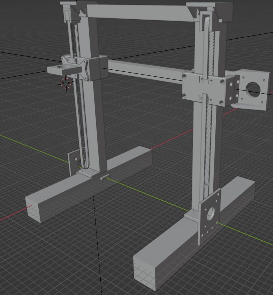
Z-Axis
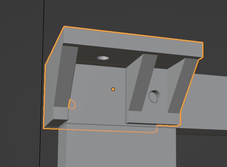
The design has 2 belts. One on each side. Here is how one side on the top looks like:
You see the original blue tensioner screws on top, which I used from the X Axis and the Y axis. I used the screws and the original tensioners for each side of the Z drive.
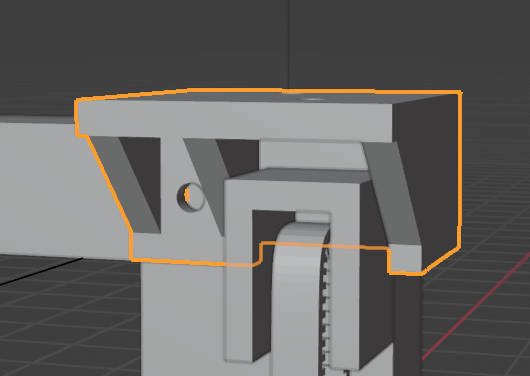
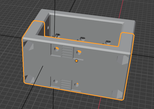
The bottom part looks like this:
Z-Drive Belt and Resolution
I am using a standard 2GT 6mm belt for the Z drive. For the motor pulleys I am using 16tooth 6mm pulleys.
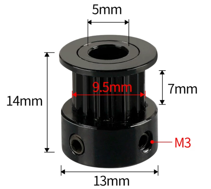
With the 16 teeth pulleys and 1/16th micro stepping, we achieve an Z resolution of 100 steps / mm which is 0.01 mm. This is absolutely enough for highest resolution print results.
The Z-Belt needs only 4 parts to print, plus the belt clamps (4x). So totally 8 parts.
Let’s define first: what is left and what is right… otherwise everyone gets confused…. I decided, as we naturally build in the parts from the backside of the printer (as the belt will be on the backside of the printer), we define what is left and right based on looking at the printer from the BACKSIDE.
Z-Drive Top Holder (Left and right)
For Mounting both holders I am using M4 8mm long BHCS Screws and T Nuts. They are smaller and fit well into the small space between the Z axis profile screws. Where there is more space, feel free to use Post Install T-Nuts. They are easier to handle.
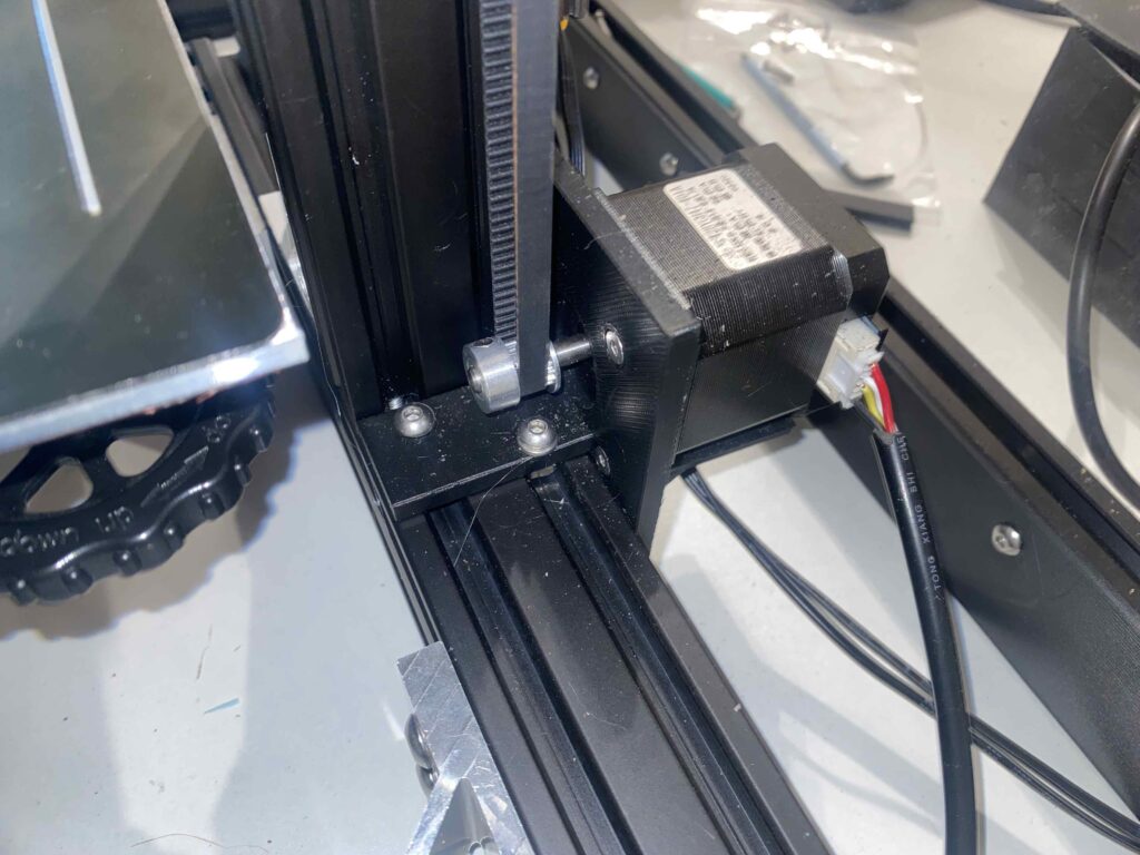
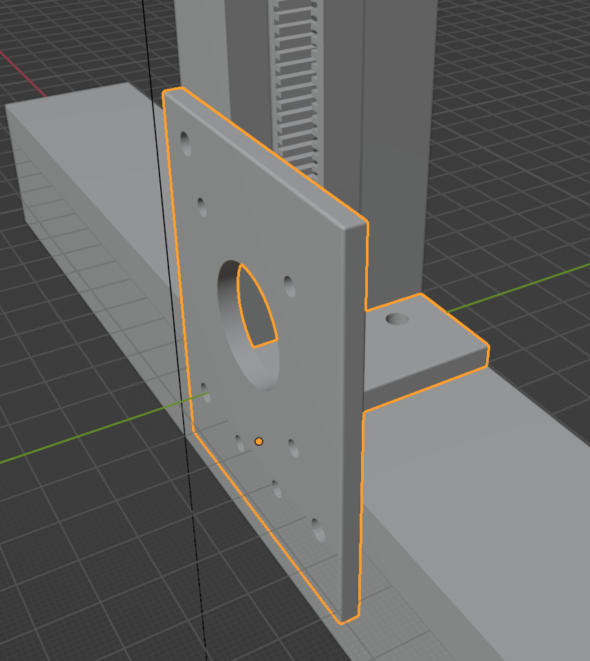
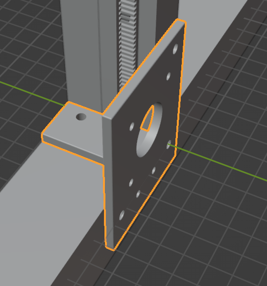
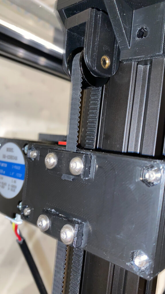
Z-Drive Motor Mount (Left and right)
For Mounting the motor plate holder I also use M4 8mm long BHCS Screws and T Nuts. And M3 of course for the Motor itself. The Plate is connected to the base profile and the Z profile to ensure highest stability. Each plate uses 3x M4 screws connected to the profiles and 4x M3 FHCS screws for the motor. Its important that thus are FHCS as the heads of those screws are in between the mount and the axis and need to “disappear”.
Z-Drive Belt Fix Clamps (4x)
The Z-Drive Belt Fix clamps attach the belts ends to the Carrier. As we have 2 belts and need for each belt 2 clamps.
Z-Rails
For the Z-Rails I am using MGN12H carriers (2x) and 2x 30cm MGN12 Rails.
X-Axis
The X-Axis is a unique design and requires a new Aluminum Profile. Its does not use the standard profile. I wanted to reuse it but it just did not work out because it needs to have the holes for the screws in different areas. The Euro 2020V is the same type as used in the original Ender 3V2 design.
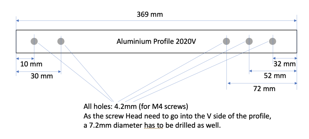
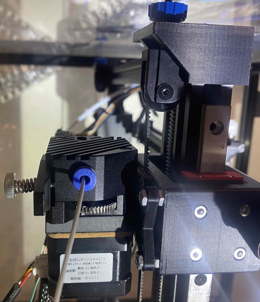
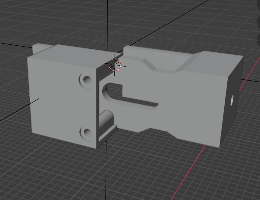
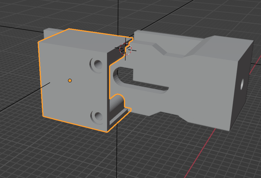
The X-Axis has the left and right side, which consists of 2 parts each side in U shape for the rail mount and the X-Axis mount as well as the belt mount and the X-Axis Motor.
Here is my left side – you see there the X-Axis motor as well. If you want to install the X-Axis motor on the right side, you just flip the parts. For a better balance of the Axis I recommend to put the extruder on one side and the Motor for the X-Axis on the other side.
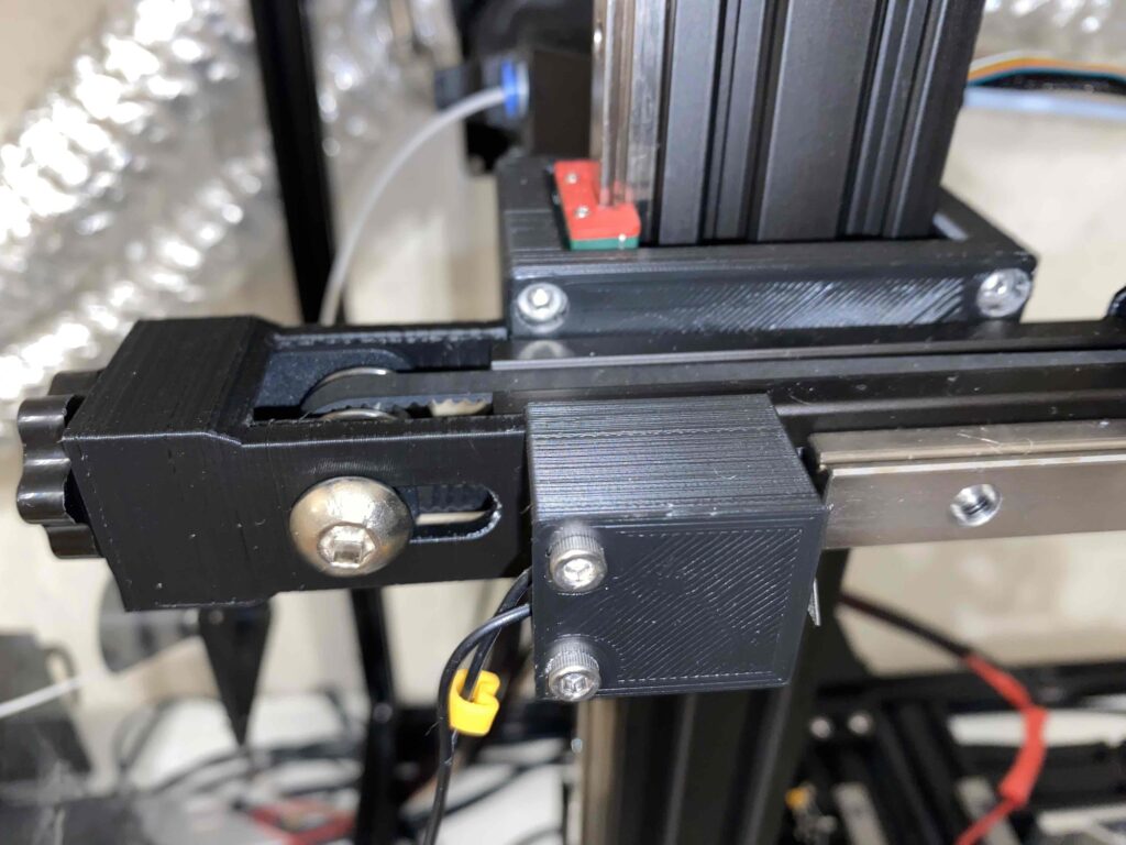
And the X-Drive from the Front of the printer:
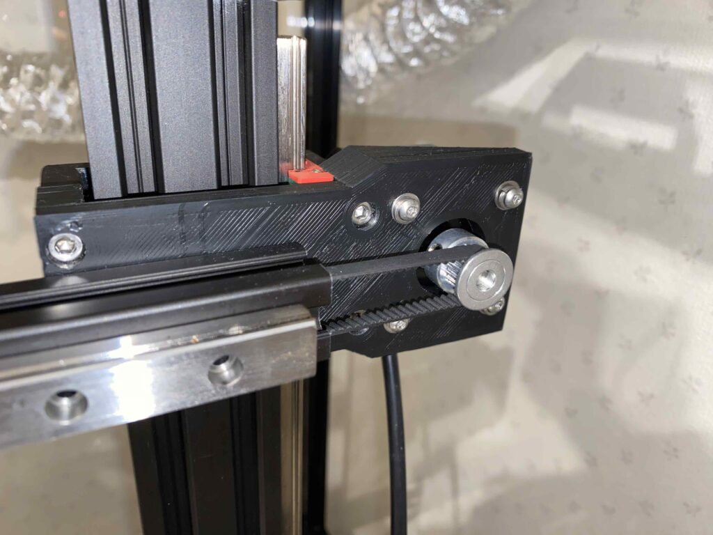
Additionally there is the Bowden Extruder mount and the X-stop as well as the X-belt tensioner:
So, lets get to the STL files…
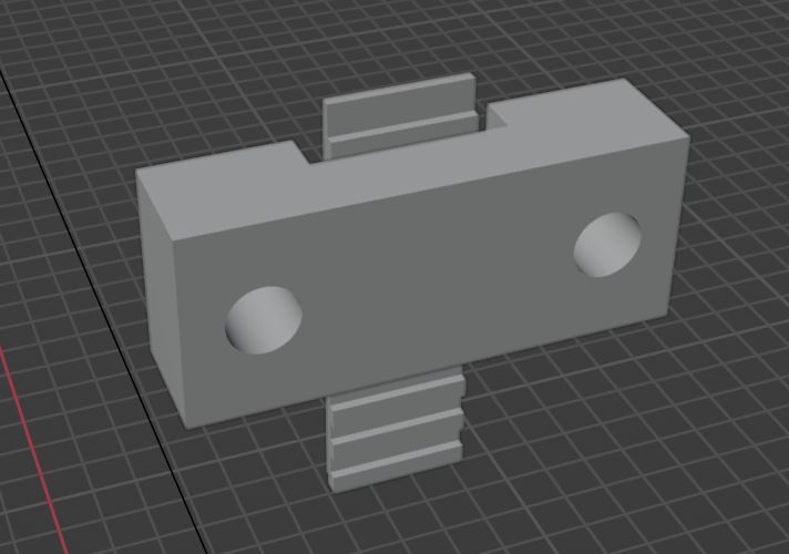
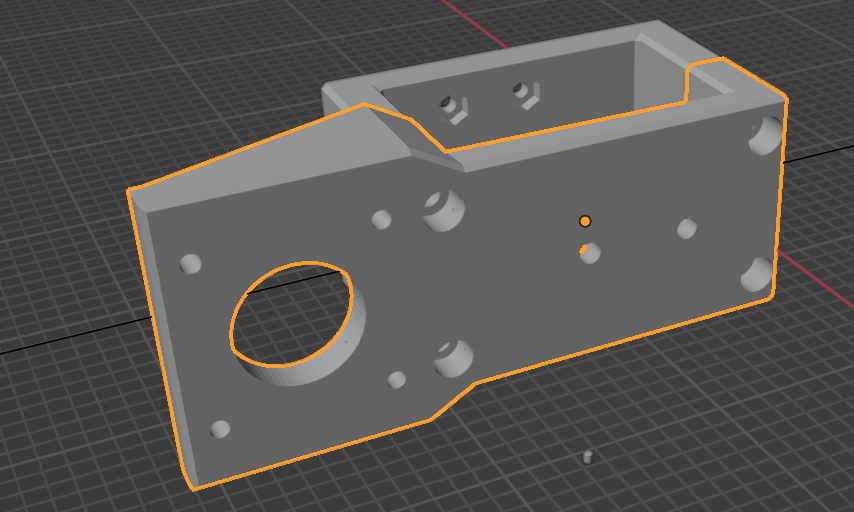
X-Axis Mount – Main (rail mount) – X-Axis Drive Side
X-Drive Motor Side. Here we have only 2 parts as the Tensioner and the X-Stop are on the other side.
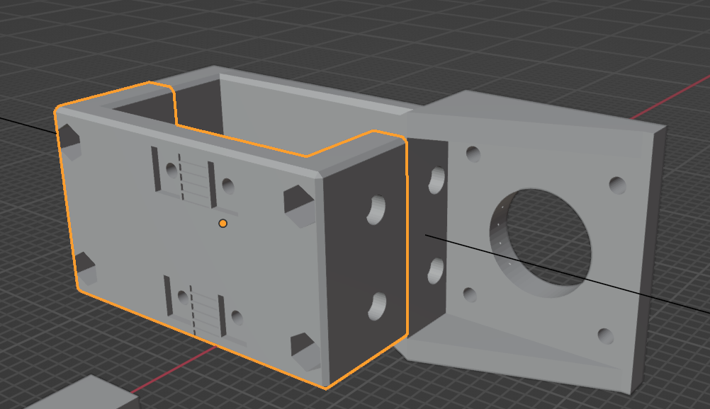
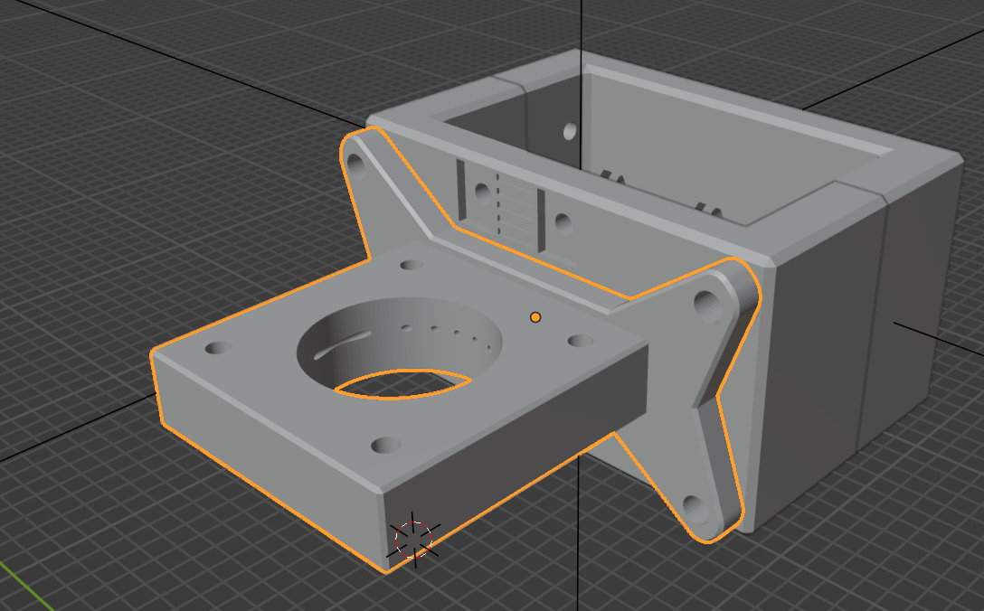
X-Axis Mount – Main (rail mount) – Extruder Side
Extruder Motor Side. Here we have 5 parts. The main rail holders:
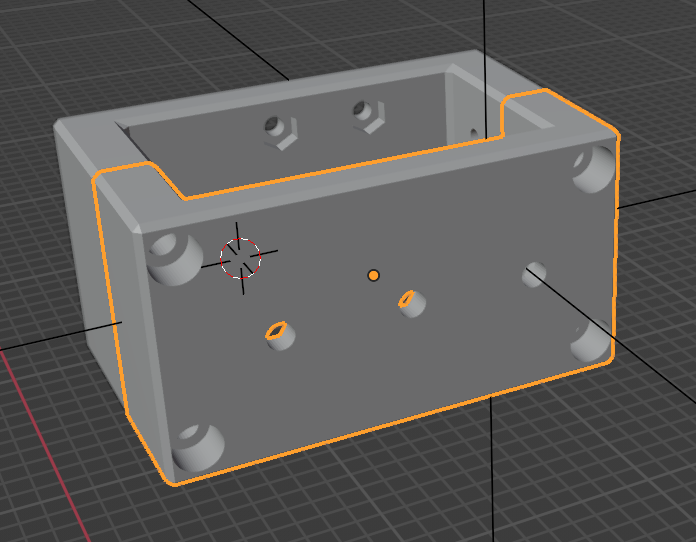
The front side is the one with the three screw holes in a row – which is mounting the X-Axis.
The Tensioner and the X-Stop:
And the Holder for the Extruder Motor:
Final comments and thoughts
It was a bit of a work to design and implement those changes. But the results are dramatically better. The only disadvantage I see since months of printing, is the fact that the X-Axis Motor holder is bending about 0.5 to 1mm which causes a little bit of rubbing off the X-Axis belt on the side of the pulley. But even if it is a little rubbing – I do not have any ringing on the prints.
The only way I thought about making it more stable would be another bigger change, and I am working on it to get this design done. It would put the X-Axis drive to the main feet of the printer – similar like the switch wire but better. Stay tuned…
And I am very happy to have your comments here. Happy to see peoples interest in my changes.
3 responses to “Ender 3-v2 Re-Engineered – Part 3: Precision Z-and X-Rail Belt Drives”
hey thanks for sharing this.
im trying to do this but it seems like there is a part missing. the top of the Z top Mount Tensioner where the belt goes over the gear
Really appreciated the clarity and depth in this piece.
Fantastic resource!
Nice share!