This is the first Video in my Ender 3-v2 Re-Engineered series. The main topic of this Video is the X-Axis Engineering solution to keep the Axis from falling into the print-bed when the motors are switched off. In a normal Ender 3-v2 printer with lead-screws, this will not happen. But when switching to high quality rails and belt drive, the X-Axis is easy to move up and down and if the motors are deactivated the axis will fall down.
The implementation need 3 kinds of changes:
- The physical structure to clink into the X-Axis at a certain height – inclusive screws and magnets
- A modification in the Firmware – I use Marlin 2 which implements the X-Axis handling
- An additional GCODE in t he slicer which handles the parking of the X-Axis when the print is done
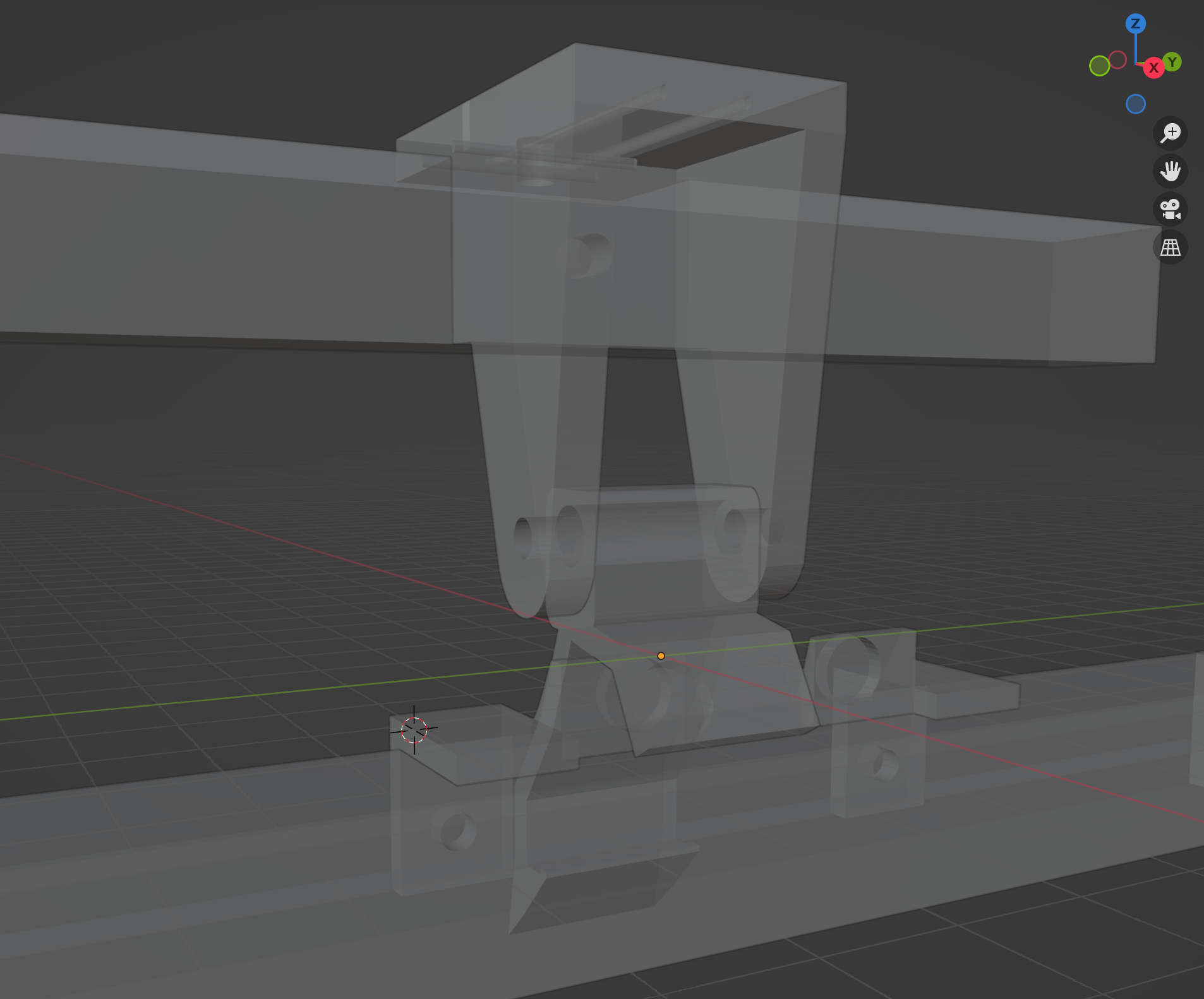
1. Physical Structure
All parts should be printed in ABS.
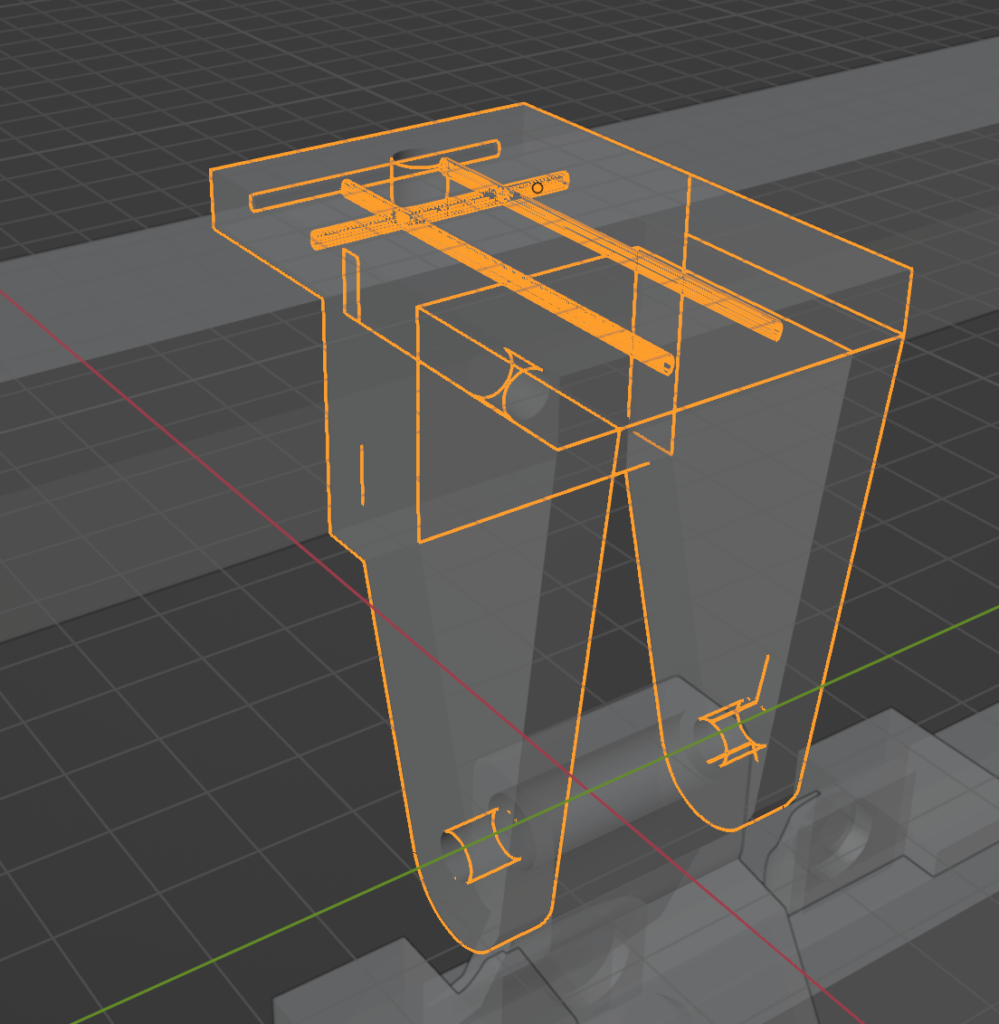
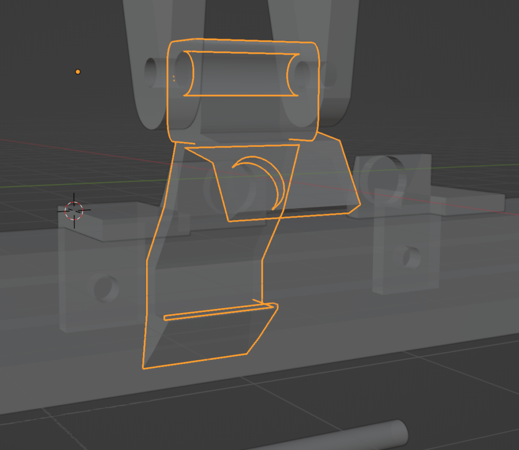
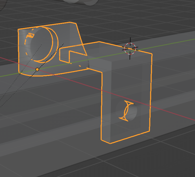
The Trigger-Right which is installed on the right side of the X-Axis
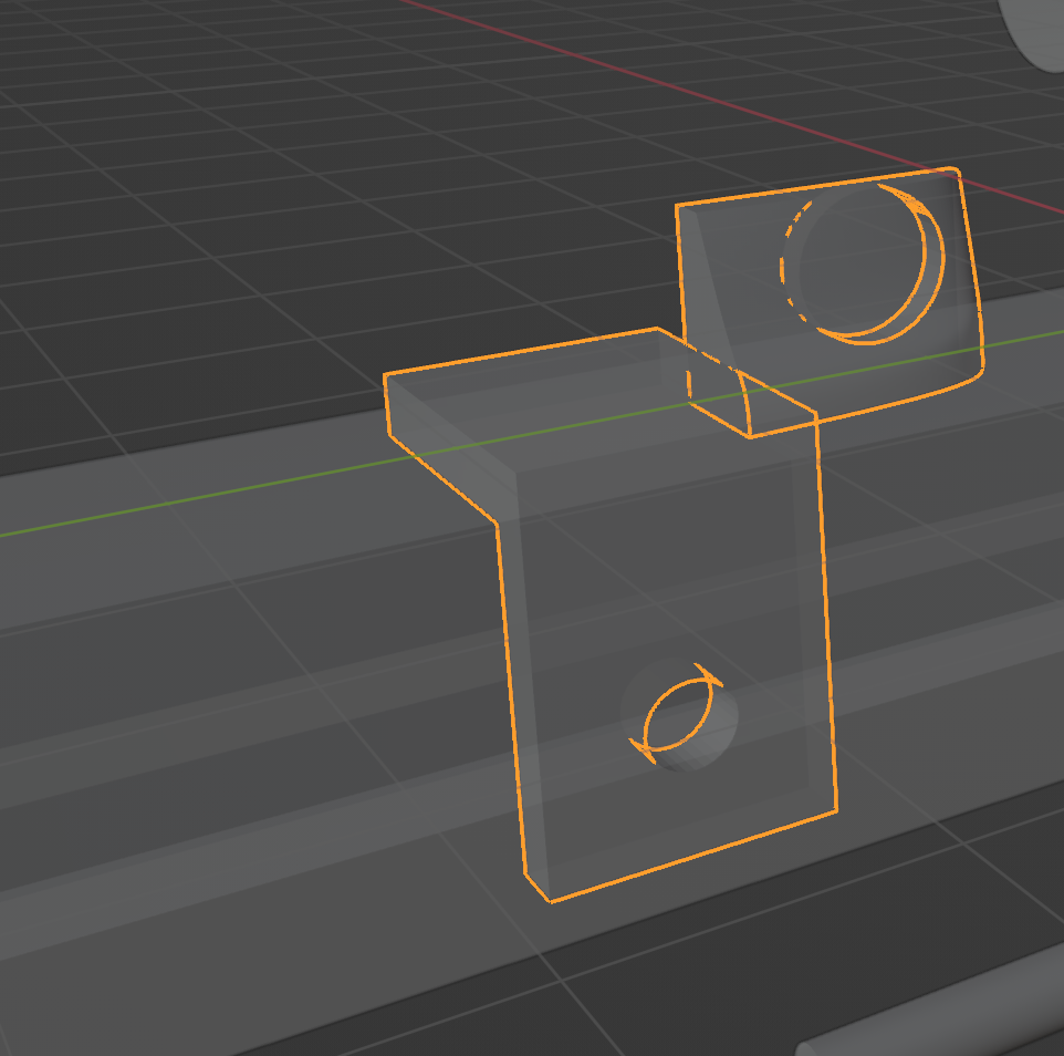
The Trigger-Left which is installed on the left side of the X-Axis
The Hooks and Triggers need to be equipped with Ferrite magnets. You need to get in total 4x 8x2mm magnets. There is no glue required. Just use a tool to squeeze them into the holes.
Why Ferrite?
- Ferrite Magnets: They are known for their good resistance to high temperatures. Ferrite magnets can typically withstand temperatures up to about 250°C. Beyond this point, they begin to lose their magnetic properties. This makes them suitable for applications where the magnet is exposed to elevated temperatures.
- Neodymium Magnets: In contrast, neodymium magnets are more sensitive to heat. Standard neodymium magnets start to lose their magnetic properties at temperatures as low as 80°C. However, there are specialized high-temperature neodymium magnets that can withstand temperatures up to about 200°C, but they are less common and more expensive.
Beside the fact we want High Temperature Environments, as we want to have the trigger also working then Printing ABS and other High-Temp Stuff, we need not powerful magnets… so Ferrite is exactly perfect for this Application.
Very important: Please take care that the 2 magnets on each side “like” each other and not push each other away! Otherwise the Trigger will not work! In case you put them wrong, you might need to print the part again.
Firmware Changes
The change in the Firmware (I am using Marlin 2) is simpler than it seams. The design makes use of the HOMING_HEIGHT. If you switch on the printer, the Z-Axis position is unknown for the Firmware. So we define in Configuration_advh.h a startup command to Home on start:
#define STARTUP_COMMANDS “M17 Z\nG28”
You need to check if it is already there. If yes maybe you need to modify it. Then we need to change the HOMING_HEIGHT. Default the value is 5mm. We add a little – 7mm is exactly what we need to trigger the Z-Holding Mechanism and release the X-Axis. This command you find in the Configuration.h:
#define Z_HOMING_HEIGHT 7 // (mm) Minimal Z height before homing (G28) for Z clearance above the bed, clamps, …
Thats already it to release the X-Axis on startup.
Now we need to make sure to park the X-Axis after print. This is something you need to add to your GCODE of your Slicer to make sure to move the X-Axis to the Z-Holding Point and after a little down so that it does not “fall” into the holder mechanism. We don’t want to add extra stress. Here is the code I use:
G90 ; Set to absolute positioning mode
G1 Z227.3 F800 ; Move Z to my measured trigger point
G1 X120 F800; Move X into the middle – so the X-Axis is better balanced.
G1 Z225.7 F100; Move Z a bit down – very close to the end.
M84 ; Disable stepper motors
We have 2 position we need to measure:
- The Trigger point of our X-Axis holding mechanism – this is when the small hook goes into the X-Axis Profile on both sides. At this positions the magnets should never trigger. In order to find this position we need to manually move up the X-Axis till it reaches this point. This point can be measured Z hight without the magnets installed (or moved out) on the X-Axis.
- From the Trigger point, we move the X-Axis slightly down in 0.1mm steps till the hooks nearly not moving anymore. This is the second point (around 2mm in total).
In order to adjust the Magnets for the release trigger in the correct way, you need to just slide the magnets on the X-Axis left and right. The best is to move the X-Axis to the first point (mentioned before) and then, move it another 5mm up (remember – we lift 7mm on startup).
Now you move the magnets in a way that it just triggers the unlock mechanism. If you think you find the right position, move the X-Axis back 5mm down (Trigger point for Hanging). The magnets still should be triggered. If you now manually push the hook towards the Profile, it should stay there and should not trigger the magnet. That setup is what we need.
Now if all done you can add for a better controllability 2 custom commands to your Code. One is: release Z, the other is Park Z.
Because for example if you interrupt your print, you might want to park it. The GCODE for parking will not be executed.
My custom commands are as follows (of course, you need to change the height and trigger points accordingly):
#define MAIN_MENU_ITEM_1_DESC “Park Z”
#define MAIN_MENU_ITEM_1_GCODE “G90\nG1 Z227.3 F800\nG1 X120 F800\nG1 Z225.7 F100\nM84”
#define MAIN_MENU_ITEM_2_DESC “Release Z”
#define MAIN_MENU_ITEM_2_GCODE “G90\nG1 Z231 F100\nG1 Z20 F800\nG28”
…. MORE TO COME… pease stay tuned…
4 responses to “Ender 3-v2 Re-Engineered – Part1 – Hang My X”
Stl very small
hi farad, yes, its maybe small. Do you face issues? Because I always use blender to design and export it as STL. Now as it is a vector file there is no loss in information based on the size. And I use usually Cura to slice. And I never had issues with the flow that the design was wrongly converted or scaled up. Otherwise I would have tried to find a way to change the STL export. What are you using?
Checked in Cura, model looks right size.
This looks to be a great build. I have just installed dual Z axis ball screw drives and have yet to run the initial test prints. It is nice to know that I can install this setup if my ball screws are not accurate enough.
Well done and thank you for sharing.